Cube Quest Robot - 2007/8 "The Cubinator"
New content added Oct 8 2008 (Scroll to end)
Cube Quest is a new robotics contest created by the Atlanta Hobby Robot Club. Two autonomous robots (not radio controlled) start from their own goal area and roam a 6—6 foot field and attempt to move red blocks back to their goal while avoiding blue blocks. Click here to see the rules.
This a new contest and no one has built any fully operational bots yet (as of Oct 9th 2007). Bots will need several sensors and a means of moving 1.5 inch square blocks.

I have under construction a Cube Quest bot that can move and navigate back and forth between the beacons as demonstrated in the video below. It lacks sensors to find blocks and avoid collisions at this time.
Cube Quest Beacon Race, March 31st 2007
Â
Here’s an overview of the sensor requirements.
Sensors required
- Polarized White Light beacon sensors (View Schematic)
- Polarization sensor
- Left/Right light sensor to navigate towards desired beacon/goal
- Vertical angle light sensor to judge distance from beacon/goal or black square detector
- Block Sensors
- Left/Right proximity sensor to navigate towards blocks
- Color sensor to determine if the block is red or blue
- Block present sensor to indicate when block is captured
- Anti-collision sensors
- Detect walls and other bots but not blocks
The polarized white light beacon sensors were designed in the spring of 2007. They are simple analog circuits made from op-amps and CDS photocells.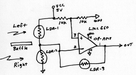
The LDR-1 and LDR-2 photocells are positioned left and right of a opaque baffle so one will be shaded more when the bot is not pointed directly towards the light source. The difference in shading will produce a voltage change at the output (pin 1). The microprocessor will use this as an error term to steer the bot towards the beacon. The output is 2.5 volts when pointed directly at the beacon. It will vary up or down as the bot turns left or right.
LDR-3 is not shaded and will vary in resistance depending on light intensity. Higher intensity will reduce it’s resistance and reduce the gain of the amplifier. This helps keep the error term more or less constant as the distance from the light source changes.
Color Sensor
The block color sensor is located directly above the block catcher as shown in the photo below. There's a red LED and a CDS photocell side by side pointing downward towards the block. Red blocks reflect considerably more red light than blue blocks so it's easy to determine which color block is present.
 |
 |
Block Color Sensor |
Block Color Sensor Schematic |
Â
Below is a photo and schematic of the reflective IR block presence sensor. It's just an IR LED and phototransistor in one black plastic package. There is not much reflectivity difference between red and blue blocks when illuminated with IR so it works for both. When a block is very close the phototransistor saturates and pulls the output voltage down near zero.
 |
 |
Reflective IR object sensor |
Schematic |
Â
Block and wall sensors
Sensors for finding blocks and avoiding walls are more complex. Here are some of the requirements.
- Must ignore ambient room light
- Must ignore polarized white light beacons
- Must ignore light emitted from sensors on other bots
- Max range needs to be only 4 to 8 inches
- Multiple sensors for identifying walls and blocks based on height
My design bounces infrared pulses off objects and measures intensity of the reflected light. It’s based on the design I used on my minisumo bot Delta Force. IR LEDs will be driven with 50 microsecond pulses to illuminate objects in the bots path. The microprocessor selects the LED pointed in the direction it wants to look and turns it on for 50 microseconds. Just before turning off the LED it grabs the A/D converter sample of received intensity and stores the amplitude value in memory. It then moves on to the next LED.
The receiver circuit is AC coupled which only allows rapid changes to reach the output. Steady or slow changes will not be detected. This eliminates room and beacon light. The IR photo diodes I’m using have built in IR pass filters to remove visible light. The pulses are 50 microseconds long repeated 1000 times per second. This is a 5% duty cycle. The bot is only looking at the world 5% of the time but updating 1000 times per second. The only possible interference issue would be active IR sensors from other bots that send continuous IR modulated in the 30 to 50 khz range. False readings can be eliminated by sanity checks and the bogus data discarded.
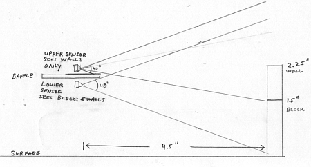
I plan to have 4 IR LED emitters with 40 degree beam widths. Two on the front and 2 on the rear. They will be pointed about 20 degrees left and right. Also there will be 4 photo diodes. Two front and rear. Two will not be shaded. The other two will have a lower baffle to limit downward views so they only see the top 1/2 inch of the wall and no blocks. The drawing below shows the vertical placement.
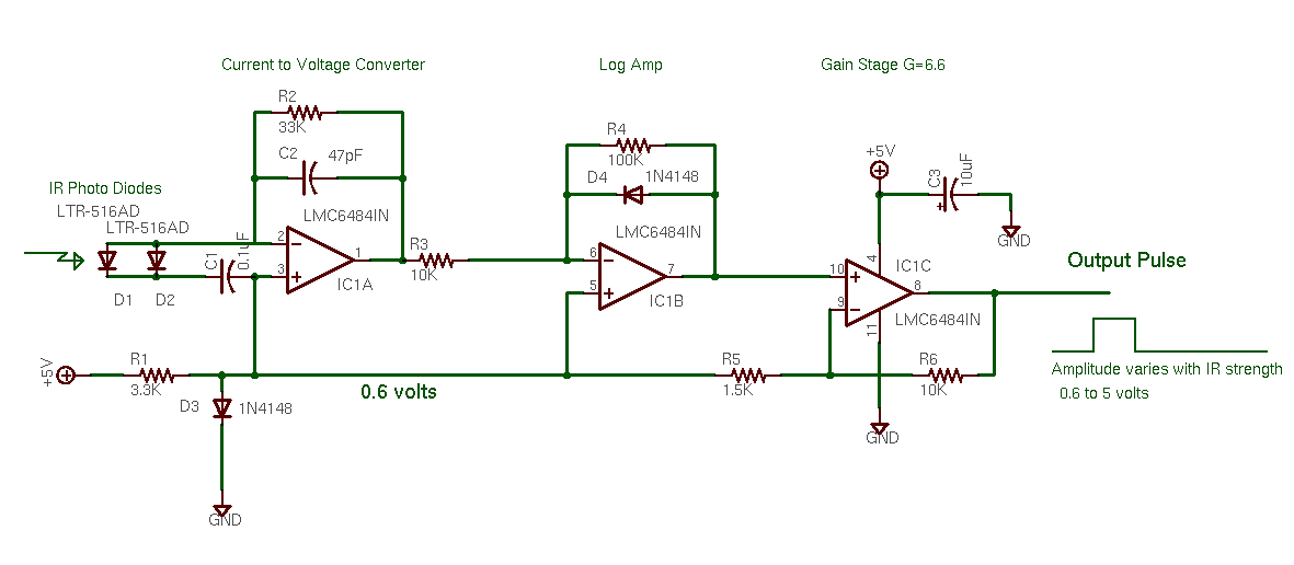
The photo diode amplifier is implemented with a LMC6484 op-amp. I’m using two, one for the upper wall sensors and the other for the block sensors. Click here to view the photo diode amplifier schematic. Note the front and rear photo diodes (D1, D2) are connected in parallel to the input. Two amplifiers serve 4 photo diodes.
 |
 |
Front Top and Bottom IR sensors |
Rear IR sensors |
Â

CDS Photocell white light sensors
Â
October 2007
After implimenting the sensors described above and writing and debugging control code for the AVR microcontroller the bot now performs the minimum actions required to play "Cube Quest".
Video of bot moving blocks into goals based on color
.
October 8, 2008
Final tweaks for AHRC Robot Rally
A year has passed with no work on this bot at all. Now it's time for the Robot Rally. For the past several days I have been testing an tweaking the bot for best performance. When it was first run after the year of sitting mostly idle it did not work.  One pin photo diode was bent and batteries were dead. After taking care of those problems others appeared. Performance was terrible. I found the braided shield on the front photo diodes was intermittently shorting to chassis ground. Also the "block present" detector cable connector had an intermittent crimp connection. The press-fit nylon hubs had become loose and there was a lot of slippage between the motor shaft and the wheel. It took a while to find and fix all those issues. Some time constants in the software required small changes as well.
Once all the broken items were repaired and the bot could sort cubes by color into respective goals I noticed other weird things.
One weirdness was the bot would try but fail to grab a block and then drag "air" to the goal.  Eventually I learned that the failure to grab happened when more than one block was in the mouth. The grabber solenoid would bang into the side of the extra block and then fail to remain actuated. Due to the low power of the solenoids I had to use a capacitor to briefly boost the voltage then drop back to the holding voltage.  So, if it failed to fully actuate intially it never would. So I need to detect the failed grab and abort the goal hunt. Easier said than done! Due to the way the sensors work I could not constantly test for block presence while dragging one to the goal. Long story... To make it sort, once a grab is done the bot moves away from the block the moves slightly forward. The block sensor retriggers verifying the block is still captured. Then we move to the goal. Crude but effective.
The next problem was due to center of mass being wrong. The bot would do a small wheely when reversing. Somtimes this banged the sensors down on a block. To prevent this I added an 8 oz counter weight in the back.
Other issues involved not pushing blocks far enough into the goals. Small changes to the code fixed that.
The bot still does some irrational things now and then but I'm declaring it "good enough" . I added a couple of plastic eyeballs and named it "Cubinator".

The Cubinator
Â
Â
Â
Â
Â
Previous page: Overthruster 30# Combat Robot
Next page: Scary-Go-Round
